
What is a WPS and which drawings should it include?
A WPS (Welding Procedure Specification) is the written document that states how to make a weld in a repeatable way: which materials are joined, with which process and consumables, in which position, with which electrical parameters and with which joint preparation.
WPS, PQR and WPQ are not the same
The three documents are related, but they answer different questions:
| Document | What it is | What it answers |
|---|---|---|
| WPS | Welding procedure specification | How must this joint be welded? |
| PQR (WPQR in ISO) | Record of the procedure qualification: the values actually used on the test coupon and the test results | What proves that this procedure works? |
| WPQ | Welder performance qualification | Is this person qualified to carry it out? |
Names and formats vary with the applicable code: ASME IX, AWS D1.1, ISO 15609-1 and ISO 15614-1, among others. Always check the edition in force for your project.
What a WPS contains
Although every format is different, almost all of them group the information into the same categories of variables. ASME IX, for example, organizes them as:
- Joints: joint design, groove type, backing, root opening, angle.
- Base metals: material, group and thickness range.
- Filler metals: classification, diameter and amount.
- Positions: of the groove or fillet, and welding progression.
- Preheat and interpass temperature.
- Postweld heat treatment.
- Shielding and backing gas.
- Electrical characteristics: current, polarity, voltage and travel speed.
- Technique: stringer or weave bead, cleaning between passes, number of electrodes.
The drawings in a WPS
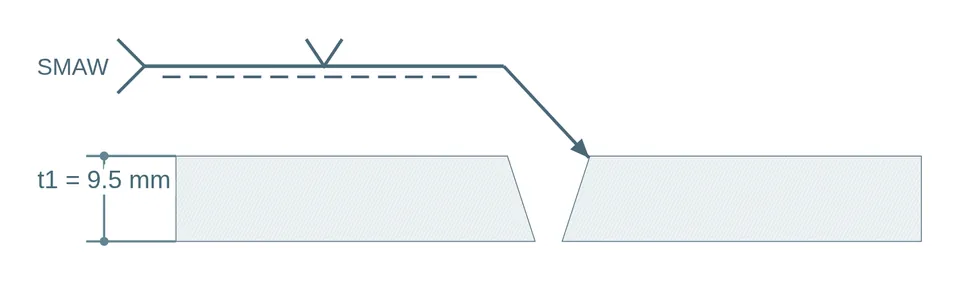
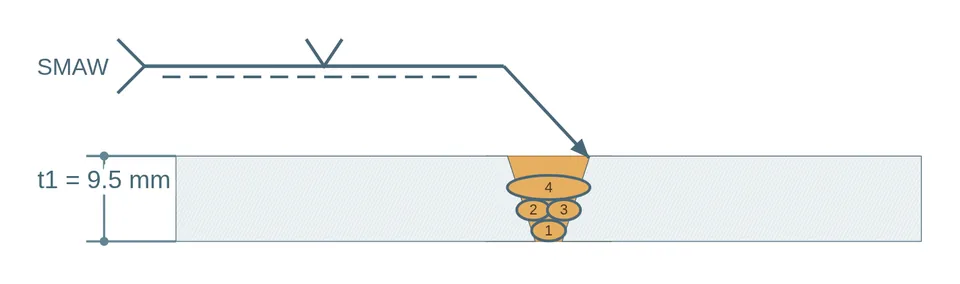
Joint design is one of those variables, and it is easier to understand drawn than described. The ASME IX suggested format (QW-482) states that sketches may be attached to illustrate the joint design, weld layers and bead sequence. The sample forms in AWS D1.1 also reserve space for joint details.
In practice, a well-documented WPS includes two sketches:
- Joint detail: thicknesses, bevel angle, root opening, root face, backing and the weld symbol.
- Pass sequence: the cross section with every bead numbered in the order it is deposited.
Common mistakes in the sketches
- Missing or ambiguous dimensions, especially the root face and the opening.
- Confusing the included angle of the groove with the bevel angle of each side.
- Pass numbering that does not match the parameters table.
- Scanned or copied images from another procedure, in low resolution.
- Weld symbols that do not follow a standard (AWS A2.4 or ISO 2553).
Checklist for your WPS sketch
- Are thickness, angle, root opening and root face shown?
- Is backing shown, and of which type?
- Does the weld symbol match the drawing?
- Does every pass have its number, matching the parameters table?
- Is the image resolution good enough to print?
Important: a good drawing does not qualify a procedure. A competent engineer or inspector validates the WPS under the applicable code.
Draw your joint in minutes
Pick from 166 geometries or 44 complete templates, adjust the dimensions and export PNG, SVG or PDF. Designing is free.